Hardware
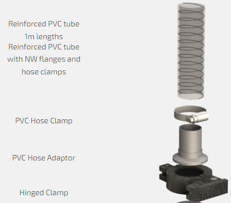
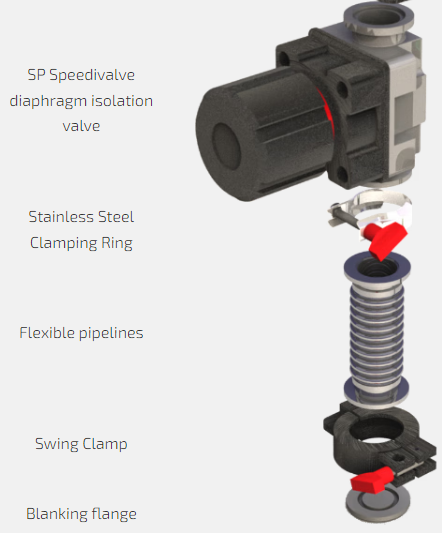
Clamps include our standard stainless steel clamping ring and our premium products – swing clamps and hinge clamps – both of which are available in polymer and aluminium and are easier to use than the clamping ring. The speedivalve is our best-selling manually operated valve and is simple to use. It incorporates indication of status and is available with either nitrile or fluoroelastomer diaphragm.
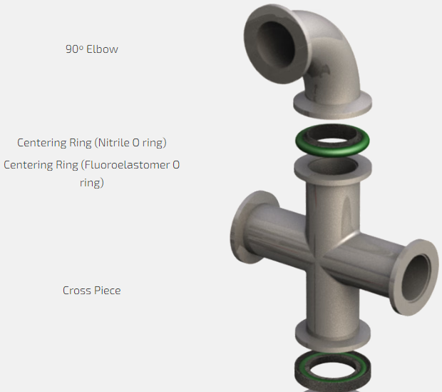
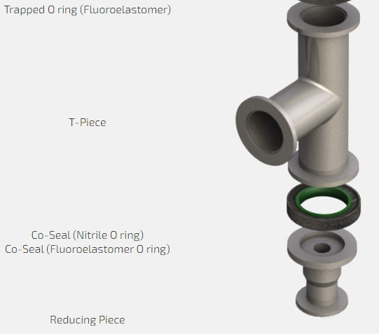
These include our standard O ring with centering ring available in either nitrile or fluoroelastomer and with polymer, aluminium and stainless steel carriers.
Material selection depends on application and outgassing, operating temperature and leak tightness requirements. Co-Seals keep the carrier out of the vacuum and thus have the added benefit of eliminating crevices and trapped volumes that can lead to instability and gas bursts. The centering rings are only designed for vacuum applications. Where some positive pressure may be seen (such as exhaust lines), Co-Seals and trapped O rings should be used. They have carriers which support the O ring on both sides, making them ideal for both vacuum and positive pressure use.
When you buy vacuum pump components from Edwards, you can expect the quality and service that only a leading international supplier can provide.
Convenience of supply: Single source supplier, able to provide the complete system solution.
High quality and reliability: Precision material control ensures a dependable vacuum performance on sensitive or demanding applications.
Comprehensive choice: Complete range for all common flange sizes in aluminium and stainless steel.
Flange Fittings Dimensions NW Dimensions
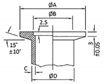
| A | B | C | D | |
| NW10 | 30 | 12.2 | 2 | 14 |
| NW16 | 30 | 17.2 | 2 | 20 |
| NW20 | 40 | 22.2 | 2 | 25 |
| NW25 | 40 | 26.2 | 2 | 28 |
| NW32 | 55 | 34.2 | 2 | 38 |
| NW40 | 55 | 41.2 | 2 | 44.5 |
| NW40 | 75 | 52.2 | 2 | 57 |
ISO Dimensions
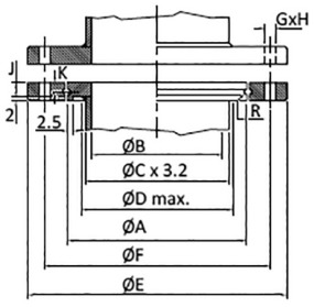
| A | B | C | D | E | F | G | H | J | K | R | |
| ISO40 | 65 | 41 | 48.3 | 2.5 | 100 | 80 | 9 | 4 | 10 | 5 | 1.5 |
| ISO63 | 95 | 70 | 76.1 | 80 | 130 | 110 | 9 | 4 | 10 | 5 | 1.5 |
| ISO80 | 110 | 83 | 88.9 | 95 | 145 | 125 | 9 | 8 | 10 | 5 | 1.5 |
| ISO100 | 130 | 102 | 114.3 | 115 | 165 | 145 | 9 | 8 | 10 | 5 | 1.5 |
| ISO160 | 180 | 153 | 160.3 | 165 | 225 | 200 | 11 | 8 | 10 | 5 | 2.5 |
| ISO200 | 240 | 213 | 219 | 225 | 275 | 260 | 11 | 12 | 10 | 5 | 2.5 |
| ISO250 | 290 | 261 | 261 | 275 | 355 | 310 | 11 | 12 | 10 | 5 | 2.5 |
| ISO320 | 370 | 318 | 318 | 355 | 425 | 395 | 14 | 12 | 15 | 7.5 | 2.5 |
| ISO400 | 450 | 400 | 400 | 435 | 510 | 480 | 14 | 16 | 15 | 7.5 | 4 |
| ISO500 | 550 | 501 | 501 | 535 | 610 | 580 | 14 | 16 | 15 | 7.5 | 4 |
| ISO630 | 690 | 630 | 630 | 660 | 750 | 720 | 14 | 20 | 20 | 10 | 5 |
ISO Flange Assembly
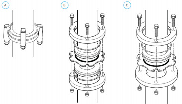
| Double claw clamps slot into a circular groove around the flange (ISO-K figure A) and secured to provide a simple but secure flange connection. The more conventional method is to use a range of bolt holes and nut/bolts with either a rotatable (ISO-F figure B) or fixed collar (figure C) flange. |
|---|
CF Dimensions
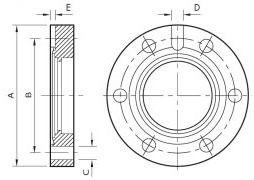
| A(mm) | B | C | D | E | Bolt Holes | |
| DN16CF | 34 | 27 | 4.4 | - | - | 6 |
| DN40CF | 70 | 58.7 | 6.6 | - | - | 6 |
| DN63CF | 114 | 92.1 | 8.4 | 6 | 3 | 8 |
| DN100CF | 152 | 130.2 | 8.4 | 6 | 3 | 16 |
| DN160CF | 202 | 181 | 8.4 | 6 | 3 | 20 |
| DN200CF | 253 | 231.8 | 8.4 | 6 | 3 | 24 |
| DN250CF | 306 | 284 | 8.4 | 6 | 3 | 32 |